Output Devices
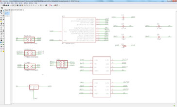
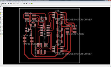
This week's assignment was to control an output device and I took this chance to advance with my final project. Since I'll have two stepper motors embedded for the token's movement I decided to familiarize myself with a stepper motor movements for this assignment. Setting up the schematics was pretty easy, but I had to be really careful with the used components and all the connected pins. As a starting design I took Neil's bipolar stepper controller and I redesigned the board by adding a communication connector. I have used Eagle for the design since I'm starting to feel comfortable with the software. After the schematics design had to switch to board layout and define all the pathways. Hawing already a little experience in designing boards without any bridges I could design it from first without any. I consider it a great success and I'm proud of the final board. It came out nicely!


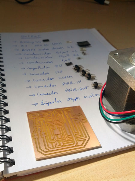
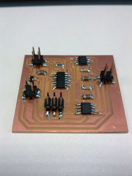
Milling the board and soldering all the components went without any problems. Only one issue to report was an unified path because of closeness. Unfortunately I haven't caught it on time and I had the board milled out like so. I simply removed the extra copper with a cutter and checked the continuity. Since it was ok I have soldered the components and the board came out as expected.


Burning the boot loader with the ISP programmer was pretty straight forward: I only had to power up the board with the power connector (didn't had FTDI connector) and connect it to the ISP programmer. Firstly I have programmed an example from the Arduino library (stepper_oneRevolution) for trying out if the stepper would move or not. I have configured the correct output pins and eliminated the SoftwareSerial output because I only wanned to see if the stepper would work or not. After connecting everything and powered up the board from a power supply (9V) the stepper started to move accordingly. Great success! My first stepper was working! Now I only had to write a little bit more complex program and try it out.
Moving the stepper (NEMA17) I have noticed a strange noise and forced movements of the motor. Re-watched Neil's video and I saw the same strange sound / movements. I have started to investigate a little bit and I figured out something. I really don't know what to make of it: the H-bridges needs a minimum 8V supply and the stepper (NEMA17) I was using needs only a 3.1 V. If my power supply is below 7.5V the H-bridges won't work, but if I'm supplying 8V input for the bridges the output pins are oscillating between 8V and -8V. This is an astonishing 16 V for a small 3.1 V motor. The same happens with my final projects steppers: they need a 7.3 V input, but with 16 V in they have forced movements. Couldn't really figured out how to reduce the output V from the bridges and for my final project I'll use the original stepper drivers that came with the order. Never less, I have programmed the controller to move the stepper one step, wait half second, move again, wait again and so on. And all these values to be sent through communication port to the PC. The feedback (steps taken) can be viewed from the Serial Monitor window.
#include < Stepper.h >
#include < SoftwareSerial.h >
SoftwareSerial serial_sw(10, 9); //rx, tx
const int stepsPerRevolution = 200;
// stepper library on pins 0, 1, 3 and 4
Stepper myStepper(stepsPerRevolution, 0, 1, 3, 4);
int stepCount = 0;
void setup() {
// initialize the serial port
serial_sw.begin(9600);
}
void loop() {
// 1 step at a time
myStepper.step(1);
serial_sw.print("steps:" );
serial_sw.println(stepCount);
stepCount++;
delay(500); // 1/2 seconds delay
}


