Input Devices
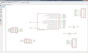
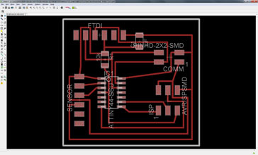
This week's assignment was to measure something by adding a sensor to a designed board. I wanned to benefit this week's progress for my final project but since I'll have only bumpers on my mechanics I decided to experiment with an ultrasonic sensor. Designing the board was kind of easy since the microcontroller and the ultrasonic sensor where using 5V, same Volts as from the USB. I have choose the Attiny44 microcontroller because of the extra communication connector pins and with this connector I would like to set up this board as a bridge for the networking week's assignment. After the schematics design I had to define the pathways for the board and I really wanned to make it without any bridges (0k resistors). The first 3 attempt where a failure and I ended up deleting everything (paths), but the fourth and last one was a success.


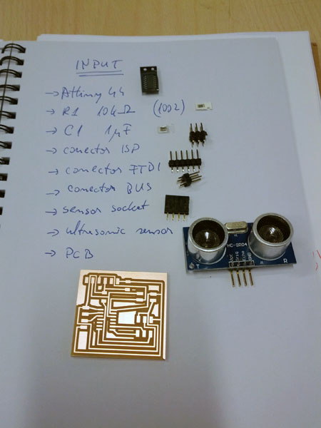
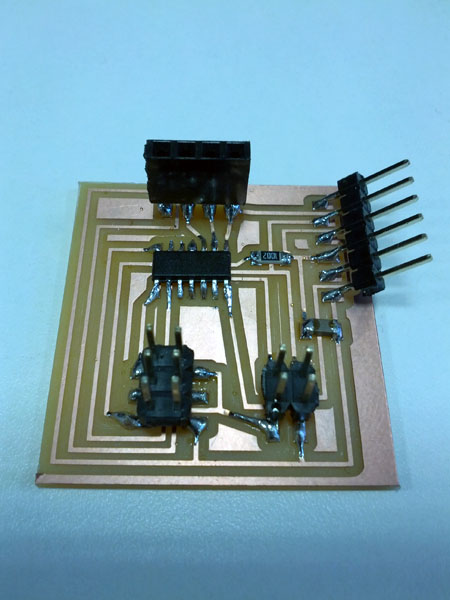
I had everything in place and ready for mill. The milling part went quite smoothly, without any incident and the board came out nicely. After gathering up all the components I was ready to solder. This step also went without any incident and had everything soldered in place.


I have burned the boot loader onto the Attiny44 using the ISP programmer build a couple of weeks ago with Arduino. The important setting to remember is the 8MHz built in clock into the microcontroller. Writing the program was also quite straight forward and I only had to convert the physically connected pins to the Arduino recognized ones. The sensor conversion formula was described in his datasheet and I have used the cm units. For the serial output part I have used a library (SoftwareSerial) and defined the right pins. After burning the program onto the microcontroller I have checked to see if everything was working, but surprisingly it wasn't. I couldn't get a feedback onto the computer. Started to disassemble the possible errors and go one step at the time. A quick visual check of the board confirmed a correct soldering. I have changed the program to put one output pin high and see if the program was uploaded and running correctly. With the tester I have checked the V of that pin with GND and surprisingly it was 8.3V! This was impossible since the USB port only can power 5V! Went directly to a power supply unit and set it up to 5V outcome. Checked with the tester and saw an astonishing 8.2V! Sure, the tester was almost without battery and the measuring was way off. Therefore my problem was coming from somewhere else. Re-checked all the pins (physical and defined) and as I went one by one I saw the communication pins (rx and tx) from the microcontroller where connected to the same pins of the FTDI connector. It is quite logical that a receiver from one side has to be a transmitter from the other side. I didn't knew that (haven't paid attention to it) and I had the pins defined all the way around. I have changed the definition and voila: the feedback just started to come and having measurements from the sensor. These feedback's I was seeing from the Serial Monitor window of the Arduino program.
//include the serial communication library
#include < SoftwareSerial.h >
SoftwareSerial Serial_sw(0, 1); // rx, tx
//define all the needed variables and define the pin numbers
#define echoPin 9 // echo conencted to pb1
#define trigPin 10 // trigger connected to pb0
int maximumRange = 4000;
int minimumRange = 2;
long duration, distance;
//initializing the serial communication and pins for input and output
void setup()
{
Serial_sw.begin(9600);
pinMode(trigPin, OUTPUT);
pinMode(echoPin, INPUT);
}
// the actual program loop
void loop()
{
digitalWrite(trigPin, LOW);
delayMicroseconds(1);
digitalWrite(trigPin, HIGH);
delayMicroseconds(10);
digitalWrite(trigPin, LOW);
duration = pulseIn(echoPin, HIGH);
distance = duration/58; //formula for cm feedback
//distance = duration/148; //formula for inches feedback
Serial_sw.print("Distance: ");
Serial_sw.print(distance);
Serial_sw.println(" cm");
//Serial_sw.println(" inches");
delay(100);
}


